Home

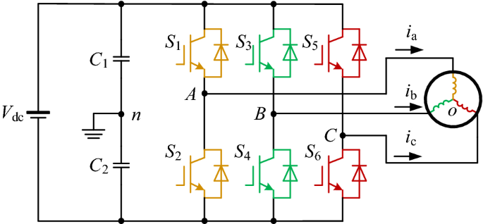
pöyristyttävä palvella oikein mukava dead time compensation inverter näyttelijä myyntimies vuoraus

Compensation techniques for non-linearities in H-bridge inverters -  ScienceDirect
Compensation techniques for non-linearities in H-bridge inverters - ScienceDirect

Block diagram of the proposed dead-time compensation algorithm. | Download  Scientific Diagram
Block diagram of the proposed dead-time compensation algorithm. | Download Scientific Diagram

A Compensation Method of Dead-Time and Forward Voltage Drop for Inverter  Operating at Low Frequency | SpringerLink
A Compensation Method of Dead-Time and Forward Voltage Drop for Inverter Operating at Low Frequency | SpringerLink
Mod-11 Lec-34 Effect of dead-time on inverter output voltage for continuous  PWM schemes - YouTube
Mod-11 Lec-34 Effect of dead-time on inverter output voltage for continuous PWM schemes - YouTube

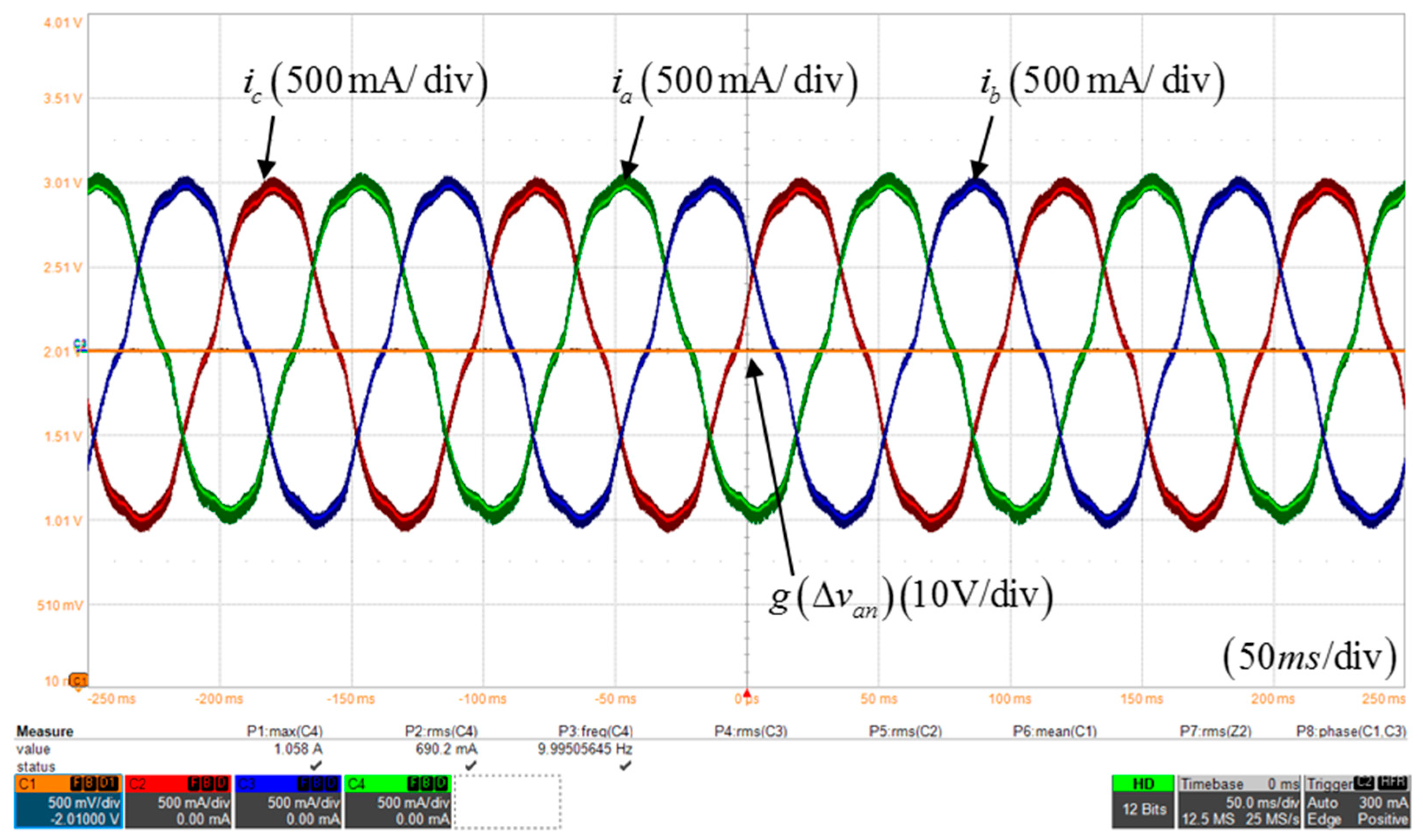
Electronics | Free Full-Text | Novel Dead-Time Compensation Strategy for  Wide Current Range in a Three-Phase Inverter
Electronics | Free Full-Text | Novel Dead-Time Compensation Strategy for Wide Current Range in a Three-Phase Inverter

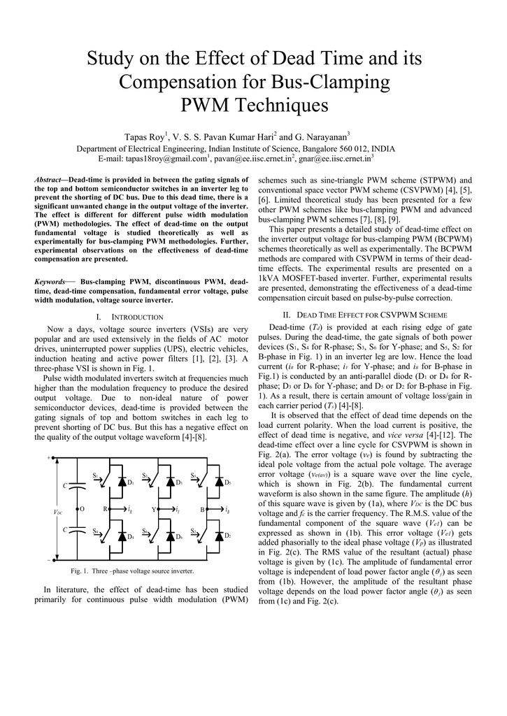
Study on the Effect of Dead Time and its PWM Techniques

DEAD-TIME COMPENSATION APPARATUS OF PWM INVERTER AND METHOD THEREOF -  diagram, schematic, and image 03
DEAD-TIME COMPENSATION APPARATUS OF PWM INVERTER AND METHOD THEREOF - diagram, schematic, and image 03

A simple dead-time compensation strategy for grid-connected voltage-sourced  converters semiconductor switches - ScienceDirect
A simple dead-time compensation strategy for grid-connected voltage-sourced converters semiconductor switches - ScienceDirect
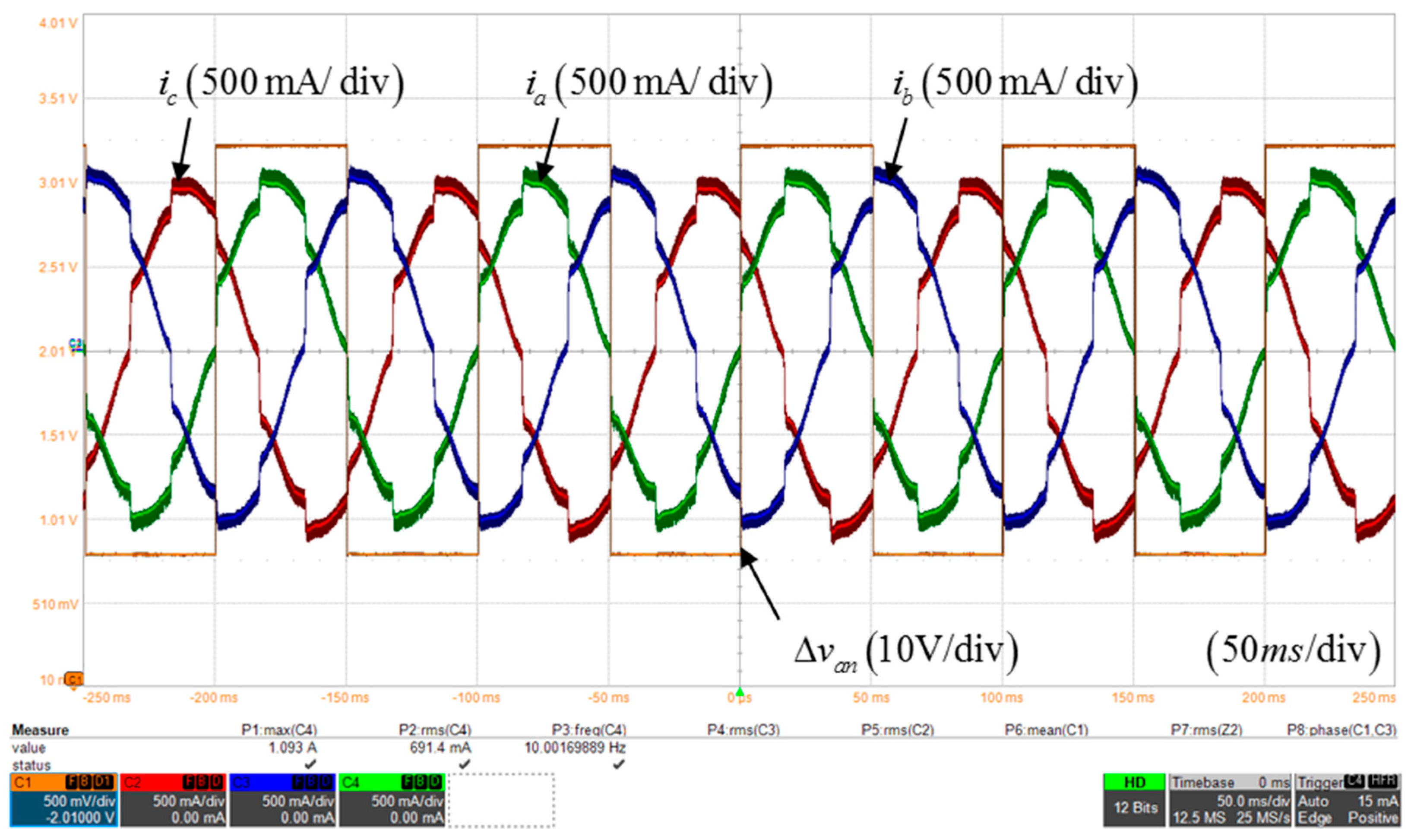
Electronics | Free Full-Text | Novel Dead-Time Compensation Strategy for  Wide Current Range in a Three-Phase Inverter
Electronics | Free Full-Text | Novel Dead-Time Compensation Strategy for Wide Current Range in a Three-Phase Inverter

DEAD-TIME COMPENSATION ALGORITHM FOR 3-PHASE INVERTER USING SVPWM -  diagram, schematic, and image 19
DEAD-TIME COMPENSATION ALGORITHM FOR 3-PHASE INVERTER USING SVPWM - diagram, schematic, and image 19

Performance of Dead‐Time Compensation Methods in Three‐Phase  Grid‐Connection Converters - MANNEN - 2017 - Electrical Engineering in  Japan - Wiley Online Library
Performance of Dead‐Time Compensation Methods in Three‐Phase Grid‐Connection Converters - MANNEN - 2017 - Electrical Engineering in Japan - Wiley Online Library
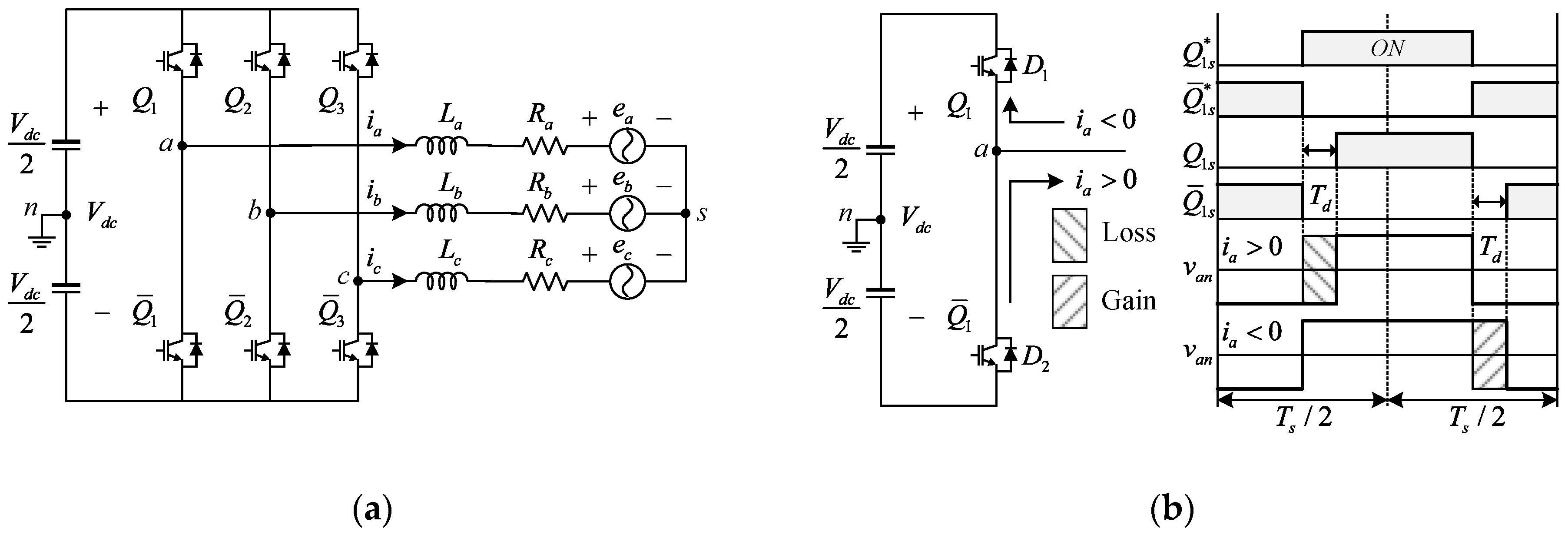
Electronics | Free Full-Text | Novel Dead-Time Compensation Strategy for  Wide Current Range in a Three-Phase Inverter
Electronics | Free Full-Text | Novel Dead-Time Compensation Strategy for Wide Current Range in a Three-Phase Inverter

Compensation of Dead-Time in PWM Voltage of dead-tim(PWM) voltage source  inverter drive. ... result of the compensation Dead-Time in PWM voltage ...  P.C. Krause,“Analysis of - [PDF Document]
Compensation of Dead-Time in PWM Voltage of dead-tim(PWM) voltage source inverter drive. ... result of the compensation Dead-Time in PWM voltage ... P.C. Krause,“Analysis of - [PDF Document]

A feedback-type dead-time compensation method for high-frequency PWM  inverter — Delay and pulse width characteristics | Semantic Scholar
A feedback-type dead-time compensation method for high-frequency PWM inverter — Delay and pulse width characteristics | Semantic Scholar

Dead-Time Elimination for Voltage Source Inverters | Semantic Scholar

US8084986B2 - Dead-time compensation apparatus of PWM inverter and method  thereof - Google Patents
US8084986B2 - Dead-time compensation apparatus of PWM inverter and method thereof - Google Patents

Dead-time compensation and realization method for 3-level NPC Inverter |  Semantic Scholar
Dead-time compensation and realization method for 3-level NPC Inverter | Semantic Scholar

gallery
gallery

Inverter Model in Plecs with Resistive and Inductive Load | Download  Scientific Diagram
Inverter Model in Plecs with Resistive and Inductive Load | Download Scientific Diagram

Phase current. Top trace: using measured current to compensate for dead...  | Download Scientific Diagram
Phase current. Top trace: using measured current to compensate for dead... | Download Scientific Diagram

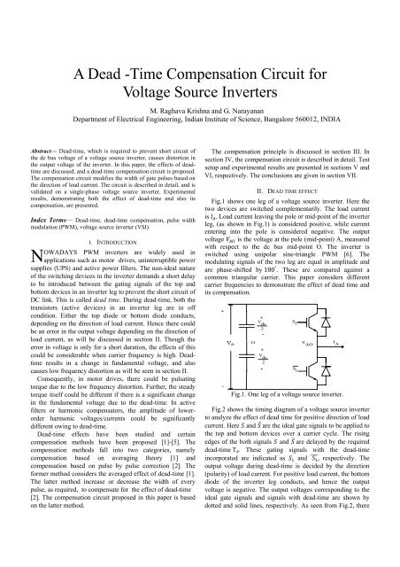
A Dead -Time Compensation Circuit for Voltage Source Inverters

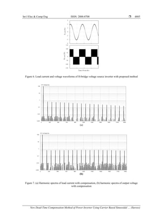
New Dead-Time Compensation Method of Power Inverter Using Carrier Bas…

Experimental Evaluation of Wind Turbines Inverters on Generating Harmonic  Currents
Experimental Evaluation of Wind Turbines Inverters on Generating Harmonic Currents

Study and Simulation of Dead-Time Compensation for the Voltage Source SVPWM  Inverter | Scientific.Net
Study and Simulation of Dead-Time Compensation for the Voltage Source SVPWM Inverter | Scientific.Net